Desertcart purchases this item on your behalf and handles shipping, customs, and support to Uruguay.
โก Unlock the power of vibration sensing โ feel the pulse of your projects!
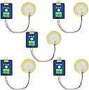
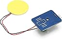
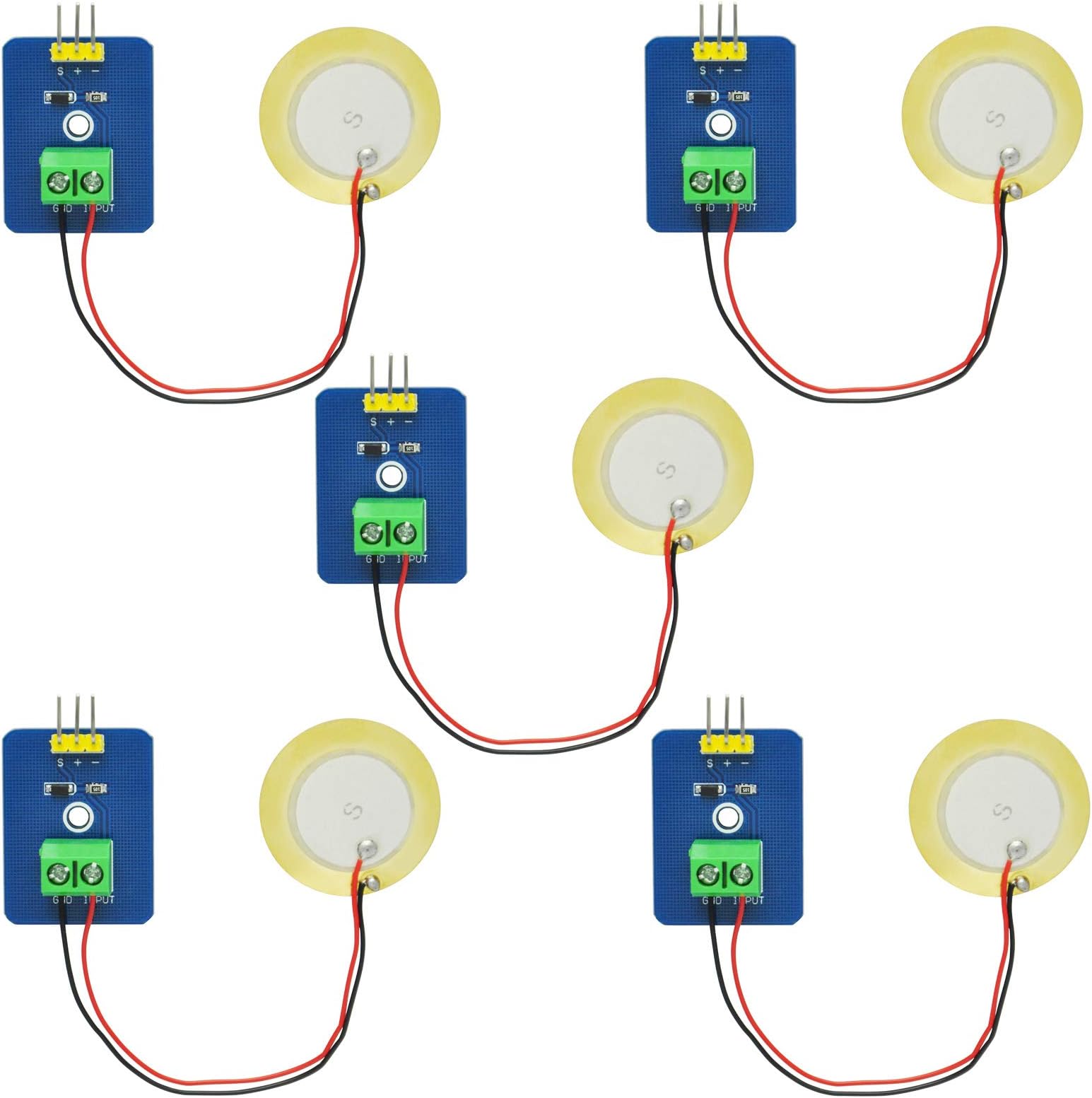
The Gikfun Analog Ceramic Piezo Vibration Sensor Module (5-pack) is a compact, PCB-mountable sensor designed for Arduino and DIY electronics. It uses a piezoelectric ceramic chip to generate an analog voltage proportional to vibration intensity, enabling nuanced detection beyond simple triggers. Operating at 3.3-5V with under 1mA current draw, it functions reliably across -10ยฐC to 70ยฐC. Ideal for interactive projects like electronic drums or motion sensing, this kit offers precision, durability, and versatility for makers and professionals alike.


| ASIN | B0829SZFBL |
| Brand | Gikfun |
| Brand Name | Gikfun |
| Centerline Length | 30 Millimeters |
| Color | Blue |
| Colour | Blue |
| Connector Type | Through Hole |
| Connector type | Through Hole |
| Customer Reviews | 4.0 out of 5 stars 31 Reviews |
| Item Dimensions W x H | 30W x 23H millimeters |
| Lower Temperature Rating | 10 Degrees Celsius |
| Manufacturer | Esooho |
| Material | Ceramic |
| Material Type | Ceramic |
| Model | EK1952 |
| Mounting Type | PCB Mount |
| Mounting type | PCB Mount |
| Number Of Contacts | 2 |
| Number Of Poles | 2 |
| Number of Positions | 3 |
| Number of contacts | 2 |
| Part Number | EK1952 |
| Upper Temperature Rating | 70 Degrees Celsius |
| Voltage | 5 Volts |
G**N
Fun little sensors, requires using an ADC
As other reviewers have mentioned, these are nice little sensors that interface well with most microcontrollers. They're very simple - the circuit board just has a 1 megaohm resistor and a diode (it's marked "W8" so could be either a Zener or Schottky diode; I'm guessing Schottky). The diode is important because piezo devices can produce very high voltages (they're used to create sparks in butane lighters!) that could damage your microcontroller. So the diode clamps the output to the positive terminal, sparing your device. The circuit boards are reasonably well made, with nice solder joints and even rounded corners. I found some of the screw terminals very stiff, but they've all worked so far. The piezo disks themselves are a commodity item, so there's not much to say, except that they only stripped off about 1/8" of insulation on the leads - I ended up stripping a bit more in order to make good contact with the terminals. Rather than rehash what others are saying, I thought I could add a bit of value by providing the kind of waveform you might expect to get from this device when used as intended. I weighted down the disk so that it was flat against a wooden desk, and then gave the desk a good firm knock while recording the output voltages. (Pardon the cheesy screenshot - I haven't set up screen capture on my scope yet). In case the picture is hard to read, each vertical division is 1 volt, and each horizontal one is 5 milliseconds. You can clearly see where the clamping diode kicks in when the amplitude is high (my power supply was set to 5 volts. The waveform is shifted down, so 0V is at the bottom of the wave). The capture starts about 2.5 divisions (12.5ms) from the left. I probably should have set the time division to show more of the "tail" of the wave, but I wanted to capture the highlights. Of course, the waveforms you get will depend on the configuration and material, but this gives you a ballpark of what you're looking for. That is, since the peaks are 5-10ms wide, you probably want to sample at at least every 2.5ms to ensure capturing them, or maybe every 1ms to be safe. The majority of the signal occurs in 50ms before it peters out. Anyway, it's always fun to play with piezos, and this kit is a good way to do it. You get plenty to play with - you can even use any spare piezos as low-quality speakers (they're high impedance, so you can just connect them directly to microcontroller pins and send out a square wave. I was able to get a tinny but audible tone from the ones in this kit). All in all, a nicely packaged kit.
Z**C
handy sensor
I am using these for hobby electronics. They are helpful and work well. No solder required for use in a pinout board. The most important thing to know is that they work. Recommend for less invasive motion sensing.
B**S
Works as expected.
No issues working with these sensors on various dev boards. The few I tested all seemed to produce consistent results. The included wires are a bit thin, but still usable. I'd consider upgrading said wires for more permanent installs or extended development use, but work fine for testing/prototyping.
T**N
No instructions or data
Typical Chinese product: no instructions or data sheet. Appears quality, but who knows? Unless you are already familiar with the product I canโt recommend it.
D**.
Fairly easy to set up. I had some issues with the screw terminals
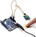
I've never used piezo-electric sensors before and I'm not an Arduino expert, but I was able to get these to a state where I could test them without too much trouble, and they work as described. There were some vague instructions in the product listing but fortunately the Arduino IDE had basically all I needed on the software side so I just had to assemble the physical connections. For anyone(especially novices like me) who wants to recreate my test setup, here's the very high level description of what I did using an Arduino UNO(generic) and the Arduino IDE 2.2.1. (The same setup could be recreated with lots of different boards or coding environments, if you have the know-how.) I connected the leads of the sensor to the screw terminals on the PCB (I connected the black wire to the GND screw, and red to INPUT.) I then stuck the 3 pin connector across the rows of a breadboard, and ran jumper wires to the UNO, connecting the PCB + to 5V on the controller, - to GND, and S to A0 (an analog input.) I then connected the UNO to my computer, opened the Arduino IDE, searched the example sketches for AnalogReadSerial (which is already set to check data from the A0 pin). I compiled and uploaded the sketch to the UNO, and then opened the IDE "Serial Plotter" tool (under Tools) to get a visual feedback of the input. If everything is set up properly, if you flick or bump the sensor, you'll see spikes in the serial data values. If you can get this setup working, then you have the fundamentals for any other projects. There doesn't seem to be a way to adjust their sensitivity within the module. They seem to have good sensitivity to detect bumps and shocks. If you need to lessen the sensitivity to filter out noise, you could probably adjust the values in the code or add a resistor in the circuit (but there's no documentation for either approach.) Other than the lack of documentation, my only complaint was the screw terminals/sensor leads. The sensor leads have very thin wires, with a very small length of wire exposed at the tip. With one of the modules, I simply haven't been able to get it to clamp on to sensor wires at all. I spent 10-15 minutes trying to position the lead wires and screw the terminal the right direction to latch onto the wire. Either the terminal was defective when I got it, or it eventually broke from my trying too hard to get it to work. I opened another module, and was able to connect the sensor to the terminals, but I was very careful about how I did it. I also tested the connection from the screw to the sensor using a multimeter just to make sure I had clamped onto the conductor, not the casing. All in all, assuming you have some basic familiarity with microcontroller programming and connecting an analog serial device, this seems to be a good set of sensors.
Trustpilot
3 weeks ago
1 month ago